The station is the heart of the watering system and will need to be robust enough to handle the readings it will receiving, store those readings, and allow users to configure the watering schedule and process from start to finish. There are many options available and I did a lot of research before landing on the configuration I selected as my first iteration.
Defining the Components
Pump
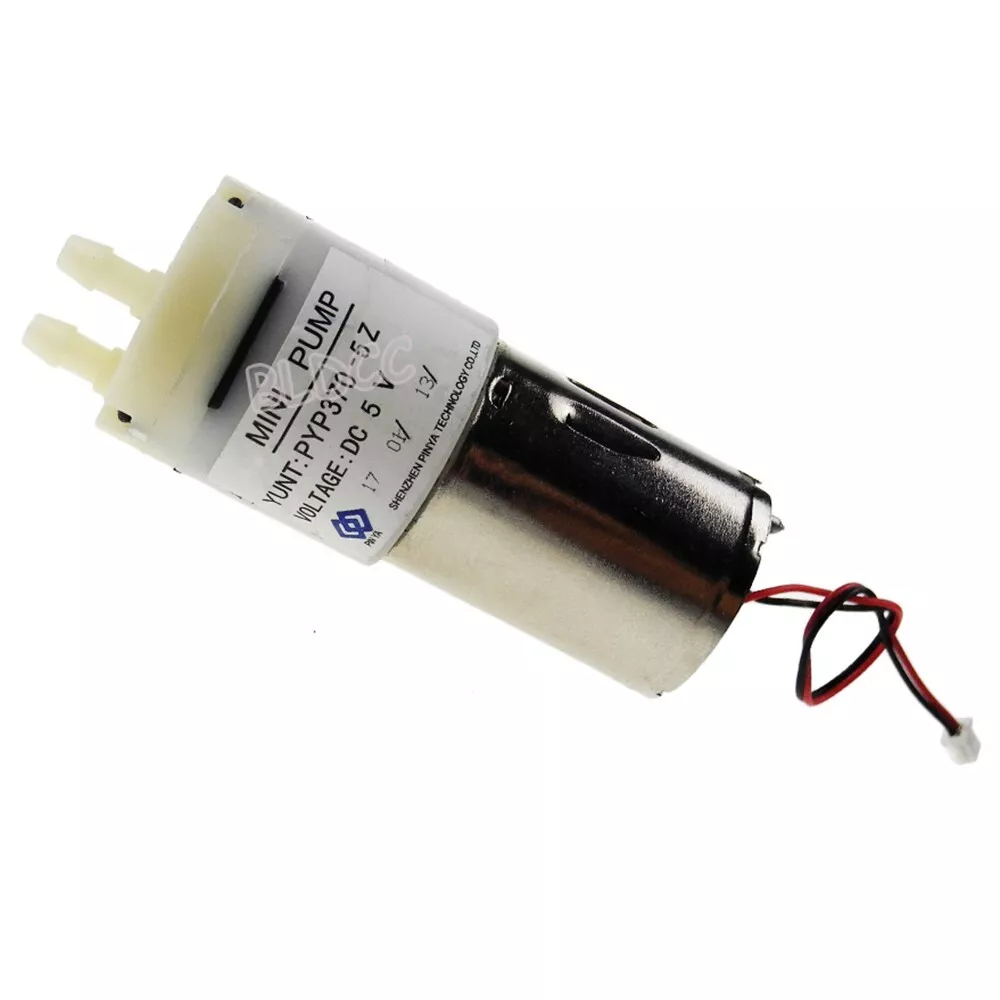
To draw water from the reservoir and distribute it to the plants, a pump will be needed. Especially with indoor watering. With exterior watering, this could probably be substituted with a hose or some other type of pressurized water source. This pump should be strong enough to draw water up from the reservoir at least over six feet of vertical distance. And the pump should be relatively quiet, so as not to create a sound nuisance in the home.
Ideally the pump will run on the same voltage at the rest of the system. When searching, I found a small pump that was pretty cheap and ran at 12V. This voltage will influence other component decisions I make throughout the project.
Valves
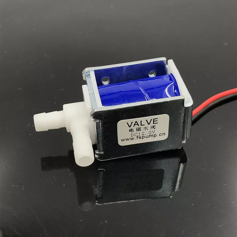
Each plant will need to have its own valve that can be opened to allow water to flow. The valve should be able to be controlled by the microcontroller so it can be opened when the sensor reports a "dry" value that should trigger a watering event.. The valve should be closed when no power is present to prevent water from flowing. And the valves should be small to prevent taking up a lot of space in the station itself.
Ideally, it should have power matching the pump to make it easier to include in the circuit.
I found a small valve that was relatively cheap that also ended up being pretty easy to fasten into a manifold once I started designing the station itself. This will make it easier to assemble and maintain the station once it's in use.
Manifold
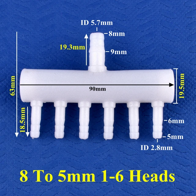
Two manifolds will be needed for this project.
- Manifold to organize the valves.
- Manifold to distribute the water source from the pump to the different valves.
I worked on a design for the valves and that will be in a future post. I also tried working on the manifold to control the water, but FDM (plastic) 3D prints aren't known for their watertight seals. It would be possible to create these on a printer, but it would probably be best, long-term, to use molded parts.
So I searched all over the internet for the size I needed and settled on these fittings from Ali Express. They have different sizes depending on how many times the source needs to be split. These are normally used for fish tanks. So they should be compatible with readily available tubing.
Bulkhead fittings
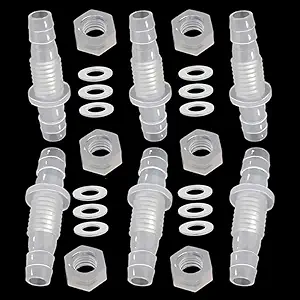
To allow the user to securely connect tubing between the station on the plants, yet again I needed to have molded parts, instead of 3D printed parts. I had tried to print a barbed fitting before, just to see if I could. And it mostly worked. But I don't want to take any chances with mixing water with electricity. So instead I found some fittings that will pass through the enclosure and screw onto the other side. It sacrifices some of the space inside the enclosure, but it ensures a secure connection between the valves and plant.
Tubing
¼” tubing to connect the reservoir to the pump, the pump to the irrigation manifold, the valves to the fittings, and the fittings to the plants themselves. I already had some on hand from previous irrigation projects around my house.
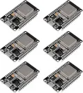
Microcontroller
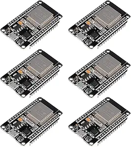
This will be the “brain” of the station and needs to have enough power process incoming sensor readings, host a web-based UI for the user to configure settings and monitor the system status, transmit readings and settings to a server (optional), and, of course, trigger watering events for each plant as needed.
Ideally this system should have storage as well, but that could also be added as needed.
For the beginning, I decided to go with a ESP32 microcontroller. They are cheaper than Raspberry Pis and accept simpler configuration.
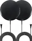
WiFi
Wireless option to allow the user to configure the station, view watering event information, and manage sensor/valve assignments. Additionally, it gives me the option to allow the user to configure the wifi controller in a familiar way (joining a private network, providing connection information, and then rebooting and connecting to the user's preferred wifi connection). Though this is a nice to have.
Wireless receiver
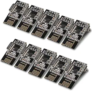
Similar to the sensor, I decided to add an RF receiver that will read incoming transmissions from sensors and pass them to the controller. This will simplify the connections, but will require additional work to ensure the sensors and stations don't have too many overlapping transmissions. This can be controlled by the channel used and I might decide to include a way for users to configure this as the sensor level using a switch or something like that.
Potential Issues
As I was building out the system, I could see that there might be issues along the way. One I could see is that when the pump would turn on, it will generate an electromagnetic field which could interfere with the wireless radios. This is especially true since the components will be included in a single enclosure, everything in close proximity. Motors have this effect and are the reason HVAC systems interrupt WiFi systems, especially since so many people place their primary WiFi systems (routers) in their garage where the HVAC systems also are often housed.

To help resolve this, I’m going to attempt to use Faraday tape to enclose the pump’s electromagnetic interference (EMI).
Another concern is the combination of water and electricity. The station will be connected to standard AC power. It would be easy to imagine the system leaking in some way and causing a safety hazard.
Fuses or breakers will be required to ensure the system is operating within safe parameters.