Intro
I knew that when I created the enclosure I would want to use 3D printing to model the final design. This was actually one of the primary reasons I purchased a printer in the first place: solve practical problems. I’ve created funnels, boxes, spacers, and other structural parts for various build projects.
This would become the most intricate design I’d built up to this point. And I learned a lot about iteration and print quality along the way.
I used Shapr3D on my iPad for all of these designs. It was intuitive, easy to use, and affordable.
Station
The Box
I started my first design for the station box in May of 2022, but I’d been looking at existing designs for over a year before that. My goal was to have the inner workings be hidden from view. Specifically I wanted to have a clean presentation. So many of these DIY projects look like projects. And that’s okay. If they solve an issue, that’s fantastic. Most of my projects have so many wirings and components out in the open on breadboards because they’re meant to be temporary or solve a specific problem.
This was going to be a bigger lift. Lots of stations all over my home. Lots of investment in this system as a whole. So I attempted to make something that would be easy to 3D print and also look good enough to be displayed or at least be visible in my home and not draw a ton of attention.
A lot of that would come down to filament choice, but I also wanted the entire enclosure to be completely enveloped so the user would only need to plug in the power and connect the irrigation tubing.
The box would need to fit the pump, valves, manifold (to split the water from the pump to the valves), the controller board, and nicely route any and all cables. Additionally, I wanted to do my best to separate any water from the controller board, and isolate the pump from the circuitry to prevent interference from the pump’s electromagnetic field. While 3D printed parts can’t be expected to be water-tight without post-processing of some kind (especially FDM parts), something is better than nothing.
Iterations
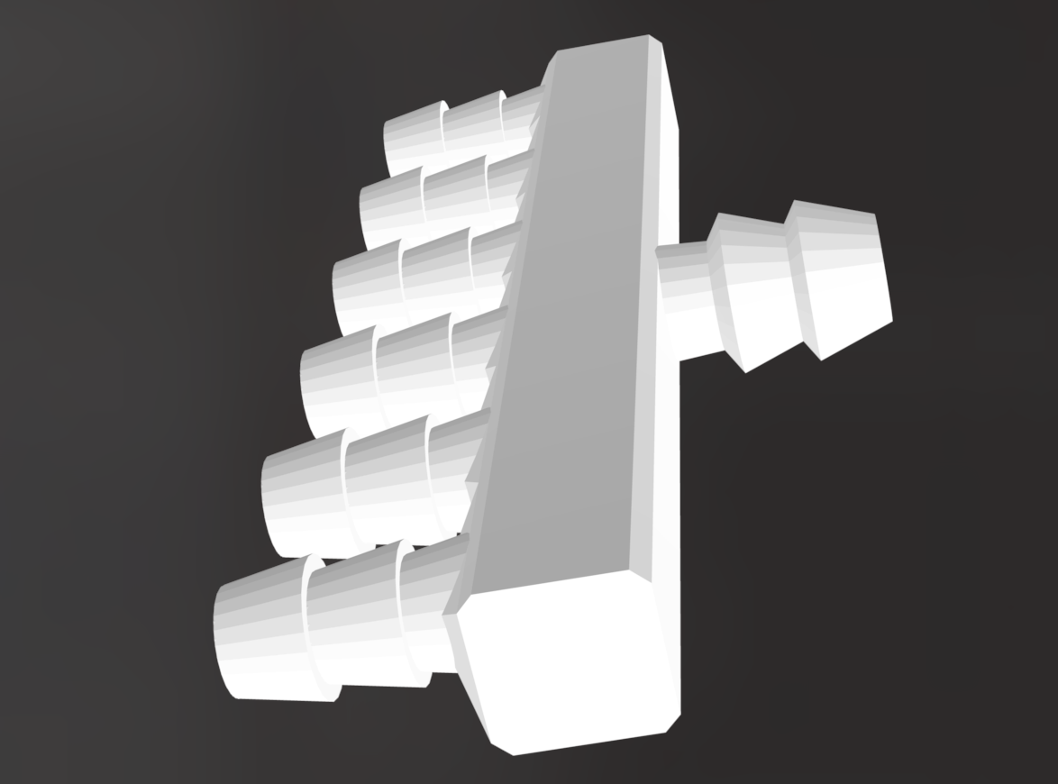
I started with a basic box and mounting standoffs for the valves. I started isolating the pump from the very beginning. The general design hasn’t really changed all that much with each version. I’ve moved around the holes in the box for the intake for tubing, changed the tolerances for the valve outputs, and moved around the power jack port position. I also modified the design a few times to provide better separation between the pump, manifold, valves, and electronics.
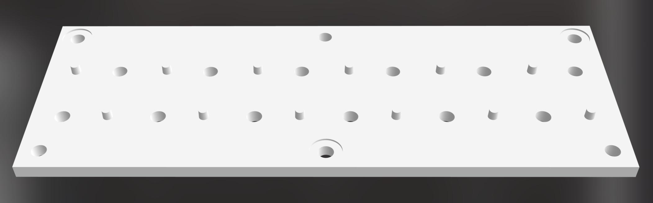
Valve Manifold
Initially I was planning on mounting the valves to the station itself. But then I realized the valves I’d purchased had threaded holes on the bottom. This made it easy to instead mount them to a manifold and then security the manifold itself to the station. It also made it easier to work on parts around the valves since they can be removed as a unit.
Water Manifold
I had initially worked on a design for a water manifold. This would distribute the incoming water from the pump to the stations. And the print turned out pretty nice. I’m still not against this option. Perhaps using resin will make a better part that I can count on more reliably for watering projects.
But I ended up going on AliExpress and finding some manifolds that were molded. They weren’t as cheap as I’d hoped, but they will work for my early prototypes.
Sensor
When creating the enclosure for the sensor, I had a few things to consider.
- Size → The sensor should be able to fit the battery and all internal parts, but also be small enough that the user can camouflage it within the plant. The goal is for the sensor to be as low profile as possible.
- Placement → The sensor would need to be near or against the soil (depending on the type of actual sensor I went with) which would mean the enclosure would need to stand up pretty well to the possibility of getting damp.
- Color → Filament choice here is likely black, unless I decide I want to call attention to the sensor itself.
- Sensor type → The sensor itself can either be a stake-like shape or prongs. The prong design has a cord which would allow the sensor to be placed well-away from any heavy contact with water.
- LEDs → These area nice to have to indicate the status of the sensor. Wet, dry, and low battery are good options.
- Switch → A switch to turn the sensor off and preserve the battery seems like a good idea so the user wouldn’t be forced to remove the battery to turn the sensor off if it’s not in use.
- Reset Button → A reset button would be a nice-to-have if a user would like to reboot the sensor and force it to send a reading to the base station.
The Design
I started the design for the sensor as a small box that would need to fit:
- The Seeeduino XIAO microcontroller
- The nrf24l01+ transceiver
- The sensor controller board
- The battery pack
- Any wiring and additional buttons/LEDs
I wanted to use a coin cell battery initially. This was from the hope to make this sensor as small as possible. Coin cells start with 3V and the largest, a CR2450, generally have a capacity of ~620mAh. After reading options on how to design the circuit for low power consumption, I’m still not opposed to this idea, however, I don’t like that I wouldn’t have readily-available rechargeable options. And I don’t like having to toss batteries all of the time from the Govee hygrometers I currently use in my home.
So I’m starting off with 2 AAA rechargeable batteries and we’ll see how far that goes.
For my initial test with the station and sensors, I won’t need the enclosure anyway, so I haven’t fully determined what this will look like. But I played around with a few different designs to get an idea for how the system could look when fully setup.
Until then it will remain in the design phase until my first tests are complete.