Welcome to Multi-Level Nerd. Today’s post features electronics and 3-D printing.
Hey everyone! Melissa here. I was cleaning my office recently because it’s gotten really out of hand. I feel like I can gauge my mental state by the state of my office. Anyway, I came across this sign my dad found at a thrift store for like one or two dollars. He says it flashes or is steady. But right now, it’s not working at all. It’s a vintage light. Battery powered with TWO C batteries. Which seems excessive for this. Also, it’s not a common size. So I’m going to modify this to get it working. And I’m going to convert it to use AA batteries instead.
Let’s get to it.
Overview
This is a simple light. There are LEDs encased in plastic and (I think) plaster and leads on the back that are wired to a battery pack. The wires are really thin. I’m impressed they haven’t been damaged before now.
The battery pack itself contains a small circuit board with electrical components and space for two C batteries. That’s a whole lot of battery for a little light. Additionally the whole thing turns on with this manual sliding switch. Moving it from side to side closes the circuit through the batteries and allows the circuit to work.
This light uses a simple electronic circuit to give options to have the light either be steady or flashing. These modes are controlled by a physical switch that alternates between two paths on the circuit board.
The stand is broken on one side and, even though we can get it to stand up, it’s not very stable.
Teardown
Board
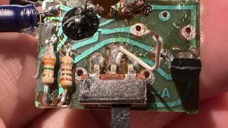
The board is small and uses primarily pass-through components (using holes on the board). This isn’t surprising because this is an old device and surface mount components didn’t really start gaining popularity until the mid-80s and late-90s. When I looked it up, it appears the majority of surface mount component technology was pioneered by IBM in the 1960s.
- https://en.wikipedia.org/wiki/Surface-mount_technology
- https://falconerelectronics.com/history-advantages-of-surface-mount-technology/
Circuit
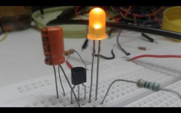
How to make world's simplest LED flasher
Watch on YouTubeThe circuit uses a basic resistor-transistor-capacitor design to control the flashing of the light. This means that there is no control over the speed of the flashing. If we wanted to get fancy, we could attach a potentiometer to the circuit to control the resistance on the circuit which would, in turn, control the speed of the flashing. Additionally, if we change out the capacitor for a larger one, it will control the speed of the flashing. But that wouldn’t make it something that a user could easily change or control.
There is also this blob of black resin on the board. At first I thought it was a glue, like hot glue. But you can see my scrape on the surface. It’s really on there and removing it would damage the circuit. I looked this up as well and this appears to be a “chip on board” (COB) technology where an integrated circuit is attached to the board (with a surface mount in this case) the IC doesn’t have any packaging on it. The resin is then added to protect the IC from damage. Based on all of the leads going into that black blob of resin, it seems like an IC. I count 9 leads attached to that thing. Since I can’t see it, I can’t talk too much about it and since this video isn’t really about breaking down everything on this board, I’m going to skip that rabbit hole.
Functionality
So the basics here is that once power is applied it has two options. When in steady mode, the power is passed directly from the source to the light, bypassing the transistor, and, I’m assuming, bypassing the large capacitor before going through the IC and eventually to ground. Note it does go through that smaller, 0.1µF capacitor no matter which mode the switch is in.
When the switch is set to flash the sign, the power is diverted through the transistor. And then it follows the path through the 160ohm resistor and, I’m assuming again, through the 4.7µF capacitor before going out to ground.
In both cases, there is a flyback diode, the T4148, that is present to prevent voltage spikes from affecting the power source. That diode appears to be similar to 1N4148 modern diodes we see in newer circuits and data sheets I reviewed appear to confirm this. The packaging is different, but the functionality is the same.
Requirements
- Fix the stand so the light is more stable.
- Protect the wiring so the battery pack and the sign are solidly connected.
- Clean up the soldering and wiring on the circuit board.
- I’d like it to use more readily available batteries (like AA).
- It still needs to work.
Design
Stand
 The stand is broken and the swiveling legs doesn’t appear to provide any useful function.
So I’m going to 3-D print a replacement. I’m using black PLA from Sunlu. I’ve designed the replacement in Shapr360 on my iPad. I find this an intuitive way to make designs like this. I’ve tried out Fusion 360, but it’s not intuitive and it drives me a little crazy. So this ends up being a good alternative. I almost added a sped up version of me creating this to the video, but it was already long, so I left the part out. Let me know in the comments if you’d like to watch my bungle my way through that…
I have battery holders for the AA batteries already. I’m going to use these to power my circuit. When I hooked it up to my desktop power supply, I saw that at 2.3V it was drawing ~500mA of current. So even though the mAh rating for AA batteries will be lower than for C batteries, it will be easier to find replacements (and rechargeable ones) to keep this light going.
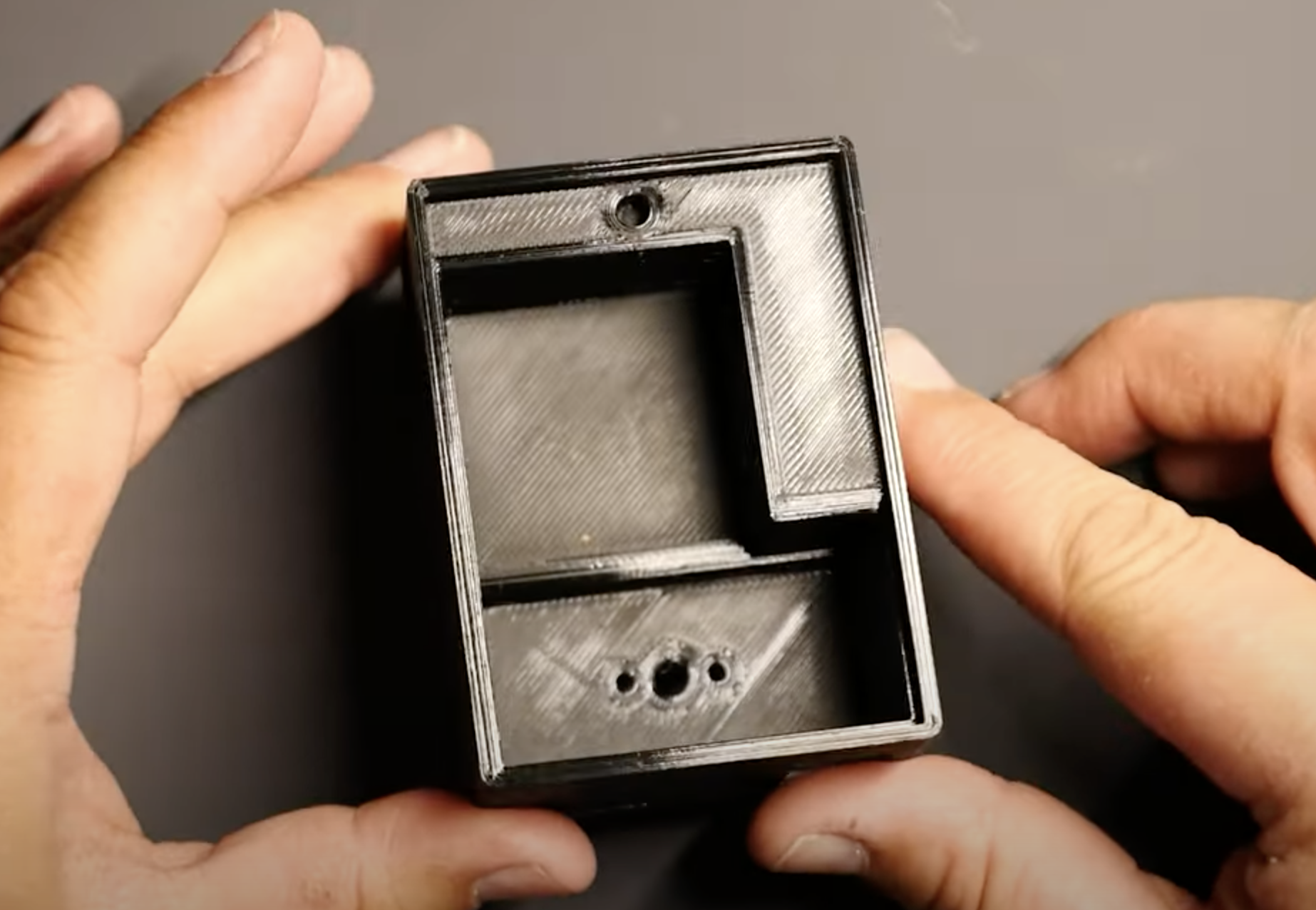
The case itself will look a lot like the old battery case, but with one difference. We’re going to combine the battery pack with a stand attached to the back of the light. This will hide the wiring and keep it from getting damaged or broken. Once it’s printed, we’ll attach it to the back of the light with some glue and remove the old legs.
Oh noooo
I started this video in January. It is now June. What happened you may ask? This. It broke off of the board. I had to search high and low for a replacement. I believe I have a good replacement. We’ll see once I install it. However, once it came, we were well into spring and I had lost my momentum from the new year. But hey. We’re here. And I’m doing better than usual. It’s been less than a year and I’m back at it. Let’s get this installed and continue with the build.
My soldering isn’t great. I don’t do this everyday. But it’s functional. And, as you can see, everything still works. So, with that repaired, let’s move on to the installation.
Board
The board will go back into this new case, with the switch readily available. I’m going to add in a rocker switch to control the power to make it more compact. I found a switch on Amazon. We’ll add it to the back of the stand next to the switch that controls the modes.
I’ve also designed a cover for the electronics to protect them during battery changes.
Assembly
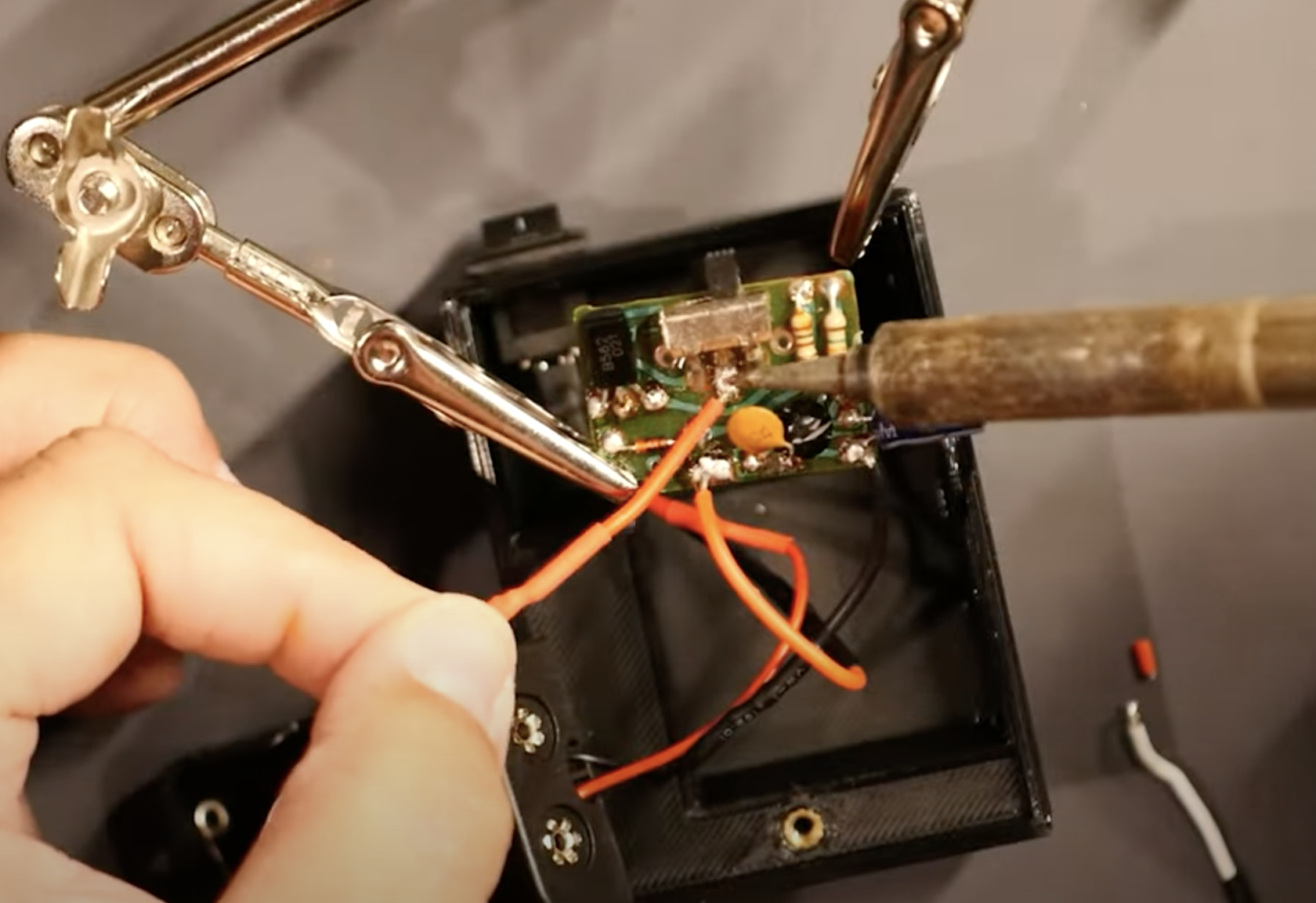 And now we have all the parts and pieces, we’re going to assemble it. I’ll feed the wires through the stand and out through the bottom. Next I add in the board and power switch. I’ll solder the power switch to the source (or power) wire from the board. Then I’ll shorten the wiring from the light to reduce the excess wire in the case. If it needs to be replaced later we can do it with modern wiring.
Then I’ll attach the shortened wires to the board, being mindful of the polarity. To do this, I’ll need to heat up the existing solder, remove the existing wire, and replace it with mine. I could use the existing wire as a jumper, but I want this to be clean. So I’ll go directly to the board.
Once the wire is ready, I’ll install the battery holders. These holders accept 2 AA batteries and I decided to add a second set in parallel to increase the available amperage. If there are four batteries, it should last twice as long. But it can work on only two.
We’ll solder the packs in parallel, attach the black negative wire to the “ground” on the circuit board and the red source or “hot” end to the VIN or power in pad on the board.
Testing
It’s all wired up and ready to go. Let’s keep the power switch off for now and add in our rechargeable AA batteries. Now we can turn it on and check if it’s working.
Let’s switch the mode to flash. Good!
Wrap up

And it’s fixed! Finally I only took me a couple of years. And a few more months. Whoops!
While I was working on this I considered doing more things to it.
- Converting it to work with solar power. But that would mean it would need to be located near a window to charge. And I didn’t really want to alter the original so much.
- Adding an arduino board to allow for smart control of the light. This was very tempting. But it would have increased the power consumption on the board. I could use different batteries and low-power modes and all of that. But in the end, it just seemed too complex for what I was trying to do.
I hope you enjoyed this video and that you’re inspired to make something today. I’d love to hear from you in the comments. Constructive criticism is always welcome.
Outro
If you enjoyed this post, please be sure to checkout my YouTube channel and consider subscribing to be updated when I add new videos in the future.
Thanks for reading!